List of the participants:
- Prof.Ella P. Shurina - leading researcher, supervisor of the project
- Yuri G. Soloveichik
- Michel E. Royak
Summary:
Methods and algorithms
The total and reduced potential calculations are performed by the finite element method on irregular tetrahedronal mesh. The method of reproduced sections is used to construct a finite element mesh. The basic mesh is constructed as Delaunay triangulation. This method permits to automate the process of tetrahedronal mesh generation.
The magnetic field of currents is represented as a superposition of the fields from tetrahedrons on which the currents is divided. The vector of current density is of a constant value and the same direction in every tetrahedron. The field from a separate tetrahedron is calculated by analytical integration. The methods and algorithms applied to dividing of currents on tetrahedrons are similar to the methods and algorithms used for the construction of a finite element tetrahedronal mesh.
A special smooth procedure is used for the calculation of magnetic induction.
Input and Output for MASTAC
The graphic means developed in MASTAC allow to construct arbitrary objects in the base section, to put the nodes with local thickening or rarity of the mesh, to edit and deform the local section without changing their topology during the replication of the basic section along an arbitrary vector or arc. In such a manner, one can build a non-surplus mesh for magnets and current coils of curved complicated configuration.
The post-processor allows to take out a potential, magnetic permeability of the ferromagnetic materials, three components and the magnetic induction modulus in the form of graphs, coloured maps and isoclinal lines in an arbitrary cross-section of the magnet.

Figure 1 General design of the dipole magnet.
An example of magnetic field calculation
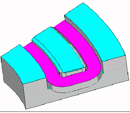
Figure 2 General view of dipole magent produced by
MASTAC viewer using MASTAC FEM tetrahedral mesh.
The precision of magnetic field calculations, its dependence on the number of mesh nodes and the capability of the pre-processor to enter the magnet geometry are illustrated by magnetic calculations of a real magnet sketched in Fig. 1,2. It is a 45o curvilinear dipole magnet with a radius of curvature of 1.12m and the complicated profile of poletips, which provides the field index n=2.7 in the 1.2-1.6 T range of magnetic fields. Besides the complicated profile, the poletips have lateral and face chamfers for the reduction magnetic induction in the neck and small chamfers at the corners for a more close fitting of current coils.
[FIGURE 3]
Figure 3 Finite element mesh on magnet boundary
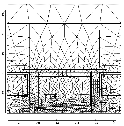
Figure 4 A mesh fragment in the base section of the magnet.
As it may be seen from Figs. 3,4 and 5, the graphic means of the pre-processor as well as the methods and algorithms used in it have allowed to describe, with high accuracy, the complicated shape of curvilinear poletips and generate automatically of the 3-D tetrahedronal mesh (64000 nodes).

Figure 5 A mesh fragment in the horizontal section of the magnet.
The results of magnetic field calculations in the longitudinal and transversal sections of the working aperture, their dependence on the number of mesh nodes are presented in Figs. 6,7,8 and 9 together with the results of the magnetic field measurements. In this figures: dash line - calculation results (16000 nodes), solid line - (64000 nodes), "(" - experimental results.

Figure 6 Field distribution of the vertical component in the midplane of the magnet.

Figure 7 Error in the computed solution as a percentage of the central field.

Figure 8 Field distribution of the vertical component in the midplane of the magnet (middle section).

Figure 9 Gradient distribution of the vertical component in the midplane of the magnet (middle section).
The calculation times (PC 486DX2-66, 16 MB) depending on the number of mesh nodes are shown in the Table 1:
| Number of nodes | 16000 | 64000 |
| Calculation time | 2 h 30 min | 11h 30 min |